CSME 11 - 15 & CSTXE 3 - 4
In this section we have taken as an example a SPI/BIOS image dump of a model which comes with CSME firmware version 11.0.x.xxxx and SKU Consumer H. However, the same applies to all CSME 11 - 15 and CSTXE 3 - 4 firmware.
From https://www.repairlap.com/forums/tools.6/ threads, you will found the correct System Tool and the Me Region and TXE Region needed.
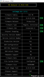
1. Open the dumped SPI/BIOS image with ME Analyzer to see what major/minor version we need as well as SKU. In this case we have:
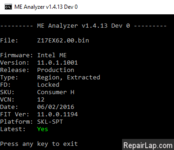
So our SPI/BIOS image dump has a CSME 11.0 firmware with Consumer SKU.
2. Browse the Repository pack, copy the same (or as similar as possible) CSME/CSTXE RGN firmware of the same SKU and major/minor version (as instructed above) somewhere and then rename it to "ME Region.bin" for CSME 11, "TXE Region.bin" for CSTXE 3, "ME Sub Partition.bin" for CSME 12 or "TXE Sub Partition.bin" for CSTXE 4, depending on what you're working with. In this case:
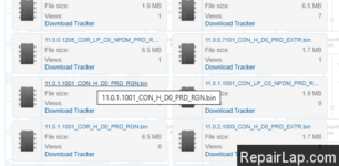
So we pick the firmware file 11.0.1.1001_CON_HXX_PRDRGN which matches perfectly what we saw at ME Analyzer. If for example the dumped SPI/BIOS image had CSME 11.0.0.1196 with LP SKU, we would have picked CSME 11.0.0.1197 instead because the one we wanted is EXTR and not RGN. Thus, we rename the "11.0.1.1001_CON_H_XX_PRD_RGN.bin" copy to "ME Region.bin".
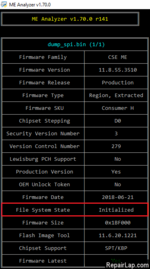
3. Open the dumped SPI/BIOS image with ME Analyzer. In order to verify that the SPI/BIOS dump has Initialization data, make sure that File System State is reported as "Initialized".
4. From the System Tools folder, go to Flash Image Tool > WIN subfolder and run fit.exe. Drag & drop the dumped SPI/BIOS image you want to clean. Go to "Build > Build Settings", select "No" at the option to "Generate Intermediate Files", leave all other settings intact and click Close.
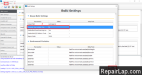
Note: If you are working on a CSME 11 Engine region only (extracted via Flash Programming Tool with "-me" parameter or via UEFITool > ME region > Extract as is...) and not a full SPI/BIOS image (Flash Descriptor + Engine + BIOS), you also need to change three additional settings. Set "Flash Settings > Flash Components > Number of Flash Components" to 0 and remove the path from both "Flash Layout > Intel(R) ME Region > Intel (R) Trace Hub Binary" and "Integrated Sensor Hub > ISH Data > PDT Binary File" only if these are not present at your dumped CSME 11 Engine region (indicated by the zero-byte size of these modules at the "Decomp" subfolder).
5. If you are working on a CSTXE 3 - 4 SPI/BIOS image, go to "Platform Protection > Platform Integrity" section.
- Check if "OEM Public Key Hash" field exists and whether it is empty/zeroed or not. If "OEM Public Key Hash" field is either missing or empty/zeroed, proceed to the next step of the guide.
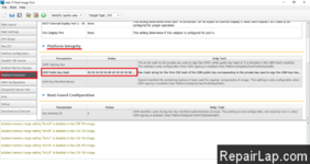
- If "OEM Public Key Hash" is populated then it is highly probable that your SPI/BIOS image is signed by the OEM and their OEM Public Key Hash is stored permanently in the Chipset hardware. In such case, you cannot easily/quickly clean the Engine firmware because the platform will reject it without the OEM's RSA Private Key.

- If you happen to have the OEM's Private RSA Key (unlikely unless you're the OEM), you can input it at "SMIP Signing Key" field. Then go to "Build > Build Settings", input the Manifest Extension Utility (MEU) executable location at "Intel(R) Manifest Extension Utility Path" field, input Win32 OpenSSL Lite 156 executable location at "Signing Tool Path" field, make sure that "OpenSSL" is selected at "Signing Tool" field, make sure that "Verify manifest signing keys against the OEM Key Manifest" is set to "Yes", leave all other settings intact and click Close. Now proceed to the next step of the guide.
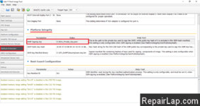
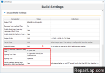
- If you don't have the OEM's Private RSA Key (expected end-user situation), you can still clean the Engine firmware section(s) of the SPI/BIOS image but more steps are needed. That's because the Engine firmware is signed independently and thus protected on its own so any FIT-configurable RSA Public Key Hashes & Signatures relate only to the rest of the BIOS/IAFW/IFWI components of the SPI/BIOS chip image. For example, the "SMIP Signing Key" found above "OEM Public Key Hash" field is used to sign/re-sign the SMIP BIOS/IAFW module which may interact with the Engine firmware but it's not actually a part of it. Thus, the goal is to update the Engine firmware only, without touching the BIOS/IAFW modules, like SMIP or DnX, which require re-signing upon rebuilding the SPI/BIOS image at FIT.
- We need to create a dummy/placeholder RSA Private Key to insert at "SMIP Signing Key" field. The use of OpenSSL is required for that. Under Windows, install Win32 OpenSSL Lite 156, go to its directory and execute the command:
1
openssl.exe genrsa --out dummy.pem 2048

- At "SMIP Signing Key" field, input the placeholder RSA Private Key (dummy.pem) that was created by the OpenSSL tool. Then go to "Build > Build Settings", input the Manifest Extension Utility (MEU) executable location at "Intel(R) Manifest Extension Utility Path" field, input Win32 OpenSSL Lite 156 executable location at "Signing Tool Path" field, make sure that "OpenSSL" is selected at "Signing Tool" field, make sure that "Verify manifest signing keys against the OEM Key Manifest" is set to "No", leave all other settings intact and click Close.
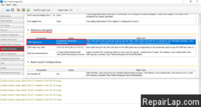
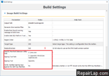
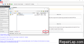
6. Go to "File > Save As" and save the configuration xml file, in this case it's named "config.xml". Afterwards, close the FIT window.
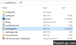
7. If you are working on a full SPI/BIOS image (Flash Descriptor + Engine + BIOS) and not a CSME 11 Engine region only (extracted via Flash Programming Tool with "-me" parameter or via UEFITool > ME region > Extract as is...), go to the FIT folder and there should now be a folder named after the inputted file, in this case it's named "Z17EX62.00". Enter "Decomp" subfolder. There should be a number of files there (BIOS Region, Flash Descriptor, OEM Region etc) including a "ME Region.bin" or "TXE Region.bin" or "ME Sub Partition.bin" or "TXE Sub Partition.bin" file. Take the previous "ME/TXE Region.bin" or "ME/TXE Sub Partition.bin" file you saved at step 4 and copy it where the current "ME/TXE Region.bin" or "ME/TXE Sub Partition.bin" file is, effectively replacing it.
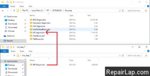
If you are working on a CSME 11 Engine region only (extracted via Flash Programming Tool with "-me" parameter or via UEFITool > ME region > Extract as is...) and not a full SPI/BIOS image (Flash Descriptor + Engine + BIOS), take the previous "ME/TXE Region.bin" or "ME/TXE Sub Partition.bin" file you saved at step 4, rename it exactly the same as the input file (Engine region) and copy it where the current input file is, effectively replacing it.
8. Run FIT again. From "File > Open" select the saved configuration xml file from step 8 and open it.
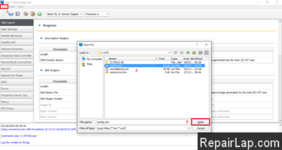
9. Click the "Build Image" icon (or "Build > Build Image") and it should complete successfully.
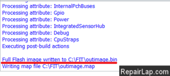
10. At the FIT folder you should now see a file named "outimage.bin" which is the dumped SPI/CSME/CSTXE image with an Engine region which has a Configured DATA section without any unneeded "Initialization" information stored.
