Toshiba Tecra Z50-A-18C Circuit diagram and boardview

andinaz73

Member (✔)
Hi
Do you have above mentioned circuait diagram and boardviev
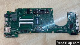
marks on the mainboard are as follow:
FALSY2
A3682A
and the text TOSHIBA (that it was produced for)
also,but obviously useless:
Hannstar MV-4-94V-0
but last remark seams useless,as I meanwhile found much very different boards on ebay and so on
so that number is for much different boards, I think

I just found once a BIOS .Bin file


BR
Andinaz73
 

andinaz73

Member (✔)
Hi
Thanks for quick reply
I bought the notebook with broken panel, changed it ,the board itself is working,but:
I don´t have the HDD Adapter to use SATA, on USB all works OK
So I just need solderpoints to connect data (just 4 signals : transmit + and - and Receive + and -) to SATA socket
The power Ground of course is no problem , and the 5V and 3,3V are also detectable around the adapter socket( Nearby capicitors)
Are there better solderpoints available for the 4 signal lines, because the original ones and the solders around are very close together,any capicitor or other parts to solder the mentioned 4 solderparts available ?
And generally question: has here transmit to be connected to transmit or receive and vice versa .
of course once the 4 solder points available with the signalnames it would be possible to find out by trying
or do you have partnumber for mentioned SATA Adapter instead
BR
Andreas
 

SAV

Member (✔)
Moderator
Hi
Thanks for quick reply
I bought the notebook with broken panel, changed it ,the board itself is working,but:
I don´t have the HDD Adapter to use SATA, on USB all works OK
So I just need solderpoints to connect data (just 4 signals : transmit + and - and Receive + and -) to SATA socket
The power Ground of course is no problem , and the 5V and 3,3V are also detectable around the adapter socket( Nearby capicitors)
Are there better solderpoints available for the 4 signal lines, because the original ones and the solders around are very close together,any capicitor or other parts to solder the mentioned 4 solderparts available ?
And generally question: has here transmit to be connected to transmit or receive and vice versa .
of course once the 4 solder points available with the signalnames it would be possible to find out by trying
or do you have partnumber for mentioned SATA Adapter instead
BR
Andreas
we can't provide such information without schematics .
 
Top Bottom